We use cookies to make your experience better. To comply with the new e-Privacy directive, we need to ask for your consent to set the cookies. Learn more.
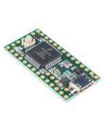
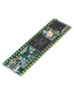
Teensy 4.1 USB ARM Cortex-M7 at 600MHz TEENSY41 DEV-16771
Special Price
PKR 13,900.00
Regular Price
PKR 14,200.00
SKU
MD-01636
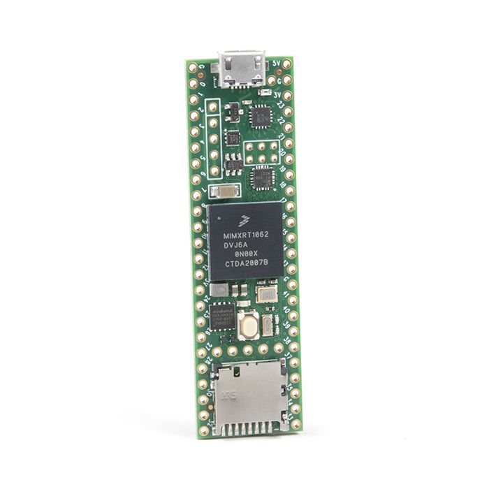
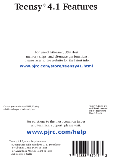
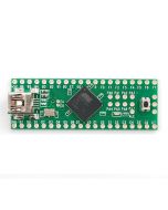
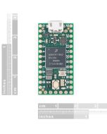
Teensy 4.1 features the fastest micocontroller and an expanded set of powerful peripherals in a 2.4 by 0.7 inch form factor. 
Teensy 4.1 can be programmed using the Arduino IDE with Teensyduino add-on.
Specifications
| Feature | Teensy 4.1 | Teensy 4.0 | |
|---|---|---|---|
| Ethernet | 10 / 100 Mbit DP83825 PHY (6 pins) |
-none- | |
| USB Host | 5 Pins with power management |
2 SMT Pads | |
| SDIO (4 bit data) | Micro SD Socket | 8 SMT Pads | |
| PWM Pins | 35 | 31 | |
| Analog Inputs | 18 | 14 | |
| Serial Ports | 8 | 7 | |
| Flash Memory | 8 Mbyte | 2 Mbyte | |
| QSPI Memory | 2 chips + Program Memory |
Program memory | |
| Breadboard I/O | 42 | 24 | |
| Bottom SMT Pads | 7 | 16 | |
| SD Card Signals | 6 | 0 | |
| Total I/O Pins | 55 | 40 | |
| Differences between Teensy 4.1 & Teensy 4.0 | |||
- ARM Cortex-M7 at 600 MHz
- Float point math unit, 64 & 32 bits
- 7936K Flash, 1024K RAM (512K tightly coupled), 4K EEPROM (emulated)
- QSPI memory expansion, locations for 2 extra RAM or Flash chips
- USB device 480 Mbit/sec & USB host 480 Mbit/sec
- 55 digital input/output pins, 35 PWM output pins
- 18 analog input pins
- 8 serial, 3 SPI, 3 I2C ports
- 2 I2S/TDM and 1 S/PDIF digital audio port
- 3 CAN Bus (1 with CAN FD)
- 1 SDIO (4 bit) native SD Card port
- Ethernet 10/100 Mbit with DP83825 PHY
- 32 general purpose DMA channels
- Cryptographic Acceleration & Random Number Generator
- RTC for date/time
- Programmable FlexIO
- Pixel Processing Pipeline
- Peripheral cross triggering
- Power On/Off management
Compare detailed specifications of all Teensy models.
Software
- Arduino IDE + Teensyduino
- Arduino's IDE software with the Teensyduino add-on is the primary programming environment for Teensy. On Windows, Linux and old Macs, Arduino is installed first and then the Teensyduino installer adds Teensy support to the Arduino IDE. On newer Macs, an all-in-one download is provided. Teensyduino includes a large collection of libraries which are tested and optimized for Teensy. Other libraries may be installed manually or by Arduino's library manager.
- Visual Micro
- Visual Micro allows use of Microsoft Visual Studio to program Arduino compatible boards, including Teensy. Only Windows is supported. Visual Micro is commercial paid software.
- PlatformIO
- PlatformIO IDE is a cross platform development environment with many advanced features. Windows, Linux and Macintosh are supported.
- Command Line with Makefile
- Makefiles for non-graphical use are provided with the Teensyduino installer.
- Teensy 4.x: {Arduino}/hardware/teensy/avr/cores/teensy4/Makefile
- Teensy LC & 3.x: {Arduino}/hardware/teensy/avr/cores/teensy3/Makefile
Processor
- Performance
- (info here)
- Dual Issue Superscaler Architecture
- (info here)
- Floating Point Unit
- The FPU performs 32 bit float and 64 bit double precision math in hardware. 32 bit float speed is approximately the same speed as integer math. 64 bit double precision runs at half the speed of 32 bit float.
- Tightly Coupled Memory
- (info here)
- Cache
- Dual 32 bit buses allow the processor to simultaneously fetch instructions and transfer data. An 8K instruction cache is used for fast code execution from flash memory.
- Branch Prediction
- (info here)
- Digital Signal Processing
- DSP extension instructions accelerate signal processing, filters and Fourier transform. The Audio library automatically makes uses of these DSP instructions.
Pins
Teensy 4.1 has a total of 55 input/output signal pins. 42 are easily accessible when used with a solderless breadboard.
This pinout reference card comes with Teensy 4.1.
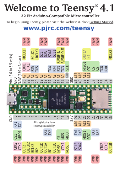
Pinout Card Files: Front Side (PDF) / Back Side (PDF)
Digital Pins
- Digital Input Pins
- Digital pins may be used to receive signals. Teensy 4.1 pins default to INPUT most with a "keeper" resistor. Teensy 4.1 pins accept 0 to 3.3V signals. The pins are not 5V tolerant. Do not drive any digital pin higher than 3.3V.
- Input Pullup / Pulldown / Keeper Resistors
- All digital pins have optional pullup, pulldown, or keeper resistors. These are used to keep the pin at logic HIGH or logic LOW or the same logic level when it is not being actively driven by external circuity. Normally these resistors are used with pushbuttons & switches. The pinMode function with INPUT_PULLUP or INPUT_PULLDOWN must be used to configure these pins to input mode with the built-in resistor.
- Pin Change Interrupts
- All digital pins can detect changes. Use attachInterrupt to cause a function to be run automatically. Interrupts should only be used for clean signals. The Bounce library is recommended for detecting changes on pushbuttons, switches, and signals with noise or mechanical chatter.
- Digital Output Pins
- All digital pins can act at output. The pinMode function with OUTPUT or OUTPUT_OPENDRAIN must be used to configure these pins to output mode. The digitalWrite and digitalToggle functions are used to control the pin while in output mode. Output HIGH is 3.3V. The recommended maximum output current is 4mA.
- Pulse Width Modulation (PWM)
- 35 of the digital pins support Pulse Width Modulation (PWM), which can be used to control motor speed, dim lights & LEDs, or other uses where rapid pulsing can control average power. PWM is controlled by the analogWrite function. 5 groups of PWM can have distinct frequencies, controlled by the analogWriteFrequency function.
- Slew Rate Limiting
- This optional feature greatly reduces high frequency noise when long wires are connected to digital output pins. The rate of voltage change on the pin is slowed. The extra time is only nanoseconds, which is enough to lower undesirable high frequency effects which can cause trouble with long wires.
- Variable Drive Strength
- (info here)
- Adjustable Output Bandwidth
- (info here)
- LED Pin
- Pin 13 has an orange LED connected. The LED can be very convenient to show status info. When pin 13 is used as an input, the external signal must be able to drive the LED when logic HIGH. pinMode INPUT_PULLUP should not be used with pin 13. TODO: SD card and QSPI pins as digital input/output
Analog Pins
- Analog Inputs
- 18 pins can be used an analog inputs, for reading sensors or other analog signals. Basic analog input is done with the analogRead function. The default resolution is 10 bits (input range 0 to 1023), but can be adjusted with analogReadResolution. The hardware allows up to 12 bits of resolution, but in practice only up to 10 bits are normally usable due to noise. More advanced use is possible with the ADC library.
- Analog Range
- The analog input range is fixed at 0 to 3.3V. On Teensy 4.1, the analogReference() function has no effect. The analog pins are not 5V tolerant. Do not drive any analog pin higher than 3.3 volts.
- Analog Comparators
- These comparators allow an analog signal to be converted to digital, with a precisely defined voltage threshold for logic low versus high.
Communication
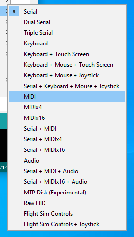
Tools > USB Type menu configures the type of USB device Teensy will implement.
- USB Device
- Teensy's primary communication is its main USB port, which operatates in USB device / peripheral mode at 480 Mbit/sec speed. The Teensyduino software supports many different types of USB communication to your PC or Mac, selected by the Tools > USB Type menu. Several of these devices types may be used simultaneously.
- Serial - Seen by your computer as a COM port (Windows) or serial device (Mac, Linux), Serial is the default and most commonly used communication type. Bytes are transfered in both directions at maximum USB speed (baud rate settings are ignored). Teensyduino has highly optimized code to allow fast USB serial data transfer. While normally used with the Arduino Serial Monitor, Teensy's USB Serial mode is compatible with software designed for serial ports, like CoolTerm. On Teensy, the seraild devices is accessed as "Serial". In the Dual & Triple Serial modes, the additional serial devices are "SerialUSB1" and "SerialUSB2".
- Emulated Serial - The USB Type settings lacking Serial use a HID interface to emulate serial. In these modes, your PC or Mac will not detect a COM port or serial device, but you can still use Serial.print() to send text to the Arduino Serial Monitor.
- MIDI - Musical Instrument Device. MIDI is often used to interface knobs, sliders and buttons to music & sound control software. MIDI messages may be sent in both directions. Teensyduino's MIDI is "class compliant" for compatibility with Macintosh, Linux, and Windows using only built-in drivers. The MIDIx4 & MIDIx16 modes provide 4 or 16 virtual MIDI ports / cables. The MIDI device name seen by your computer may be customized.
- Audio - Bi-directional stereo audio streaming, seen by your computer as a USB sound card. Using your computer's sound preferences, programs which play sound can stream to Teensy, and programs which record or process sound can receive, as if you were using a USB microphone. USB Audio is meant to be used together with the Teensy Audio Library, allowing your computer's sound to integrate with any audio processing system you design on Teensy.
- Keyboard - Standard 104 key USB keyboard. Programs can transmit keystrokes to your computer, allowing control of nearly any software. Media control keys (play, pause, volume, etc) may also be used. Many non-US keyboard layouts are supported, using the Tools > Keyboard Layout menu.
- Mouse - A special USB mouse is emulated. Both relative motion of a normal mouse, and absolute screen position similar to a digitizer pen can be sent to your computer. Mouse buttons and scroll wheel are also supported.
- Joystick - A joystick / game controller with 6 axes (X, Y, Z, Zr, Slider1, Slider2), 32 buttons, and 1 hat switch are supported. The Joystick type is useful for controlling games or other software which responds to a joystick.
- Touchscreen - Emulates a touchscreen capable of detecting up to 10 finger positions.
- MTP Disk - Media Transfer, seen by your computer as a phone or camera which shares files.
- Flight Sim - Allows integration with the X-Plane flight simulator software. Variables and controls within the simulator are linked to variables in your code running on Teensy.
- Raw HID - Allows communicating 64 byte messages with custom written software on your computer.
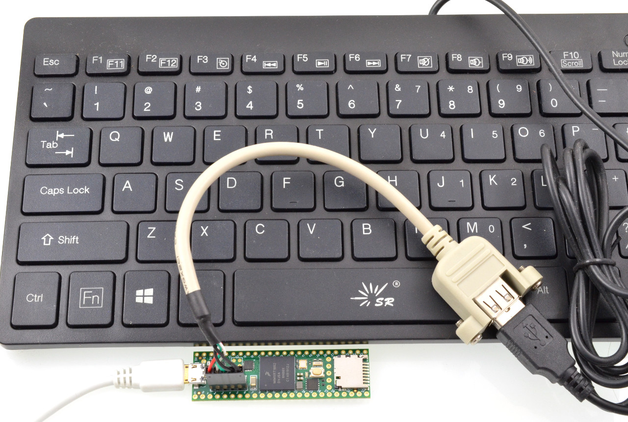
- USB Host
- A second USB port operates in host mode, which allows you to connect USB devices to Teensy 4.1. It is fully independent of the main USB device port, so USB devices you connect on the host port can simultaeously communicate with Teensy while Teensy communicates with your computer via the USB device port. This USB host port runs at 480, 12 or 1.5 Mbit/sec, depending on the speed if the device you connect. USB hubs may be used to connect many USB devices. The USBHost_t36 library is used for the USB host port. This USB host cable is normally used to connect a USB device or hub.
- Serial
- 8 serial ports allow you to connect serial devices, such as MIDI, GPS receivers, DMX lighting, ESP wireless modules, etc. All 6 serial port are fully independent and can transfer data simultaneously. None are shared with USB (as is done on some Arduino boards). All 8 ports include FIFOs for better performance at high speed baud rates.
- I2C
- 3 ports for I2C (signals SDA & SCL) allow connecting a wide variety of chips which use I2C communication. The Wire library is used for I2C. Each I2C chip connected to the same SDA/SCL wires needs a unique address. Multiple I2C ports allow you to easily use more than 1 chip with the same address. All I2C ports support 100, 400, and 1000 kbit/sec speeds.
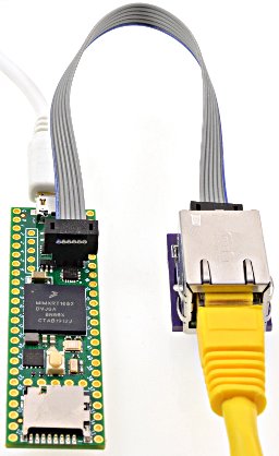
Ethernet Kit on Teensy 4.1
- SPI
- 3 ports for SPI (signals MOSI, MISO, SCK) allow connecting higher speed chips, SD cards, and displays which use SPI communication. The SPI library provides software support for SPI. The first SPI port features a FIFO for higher sustained speed transfers. Each SPI chip requires a chip select (CS) signal. Most libraries using SPI can use any digital pin. The SPI ports provide special hardware controlled CS pins, which are used by specially optimized libraries for higher performance.
- CAN
- 3 ports for CAN bus allow connecting to automotive & industrial control systems which use CAN communication. A CAN transceiver chip must be added to complete the electrical interface between Teensy 4.1 and the CAN bus.
- FlexIO
- (info here)
- Ethernet
- Teensy 4.1 contains an Ethernet controller and Ethernet PHY chip. To connect an Ethernet cable, only this RJ45 magjack kit is needed. Ethernet can also be implemented using the Wiznet W5500 and Wiz820 shield, connected to the SPI port.
Displays
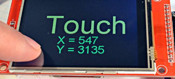
ILI9341 Color TFT Display The best supported display for Teensy 4.1
- ILI9341 320x240 Color TFT
- These displays are the best supported on Teensy 4.1, with multiple high performance libraries for fast updates speed. ILI9341 is usually the best display to use, due to superior software support.
- ST7735 Color TFT
- These displays are slightly smaller and lower resolution than ILI9341. Highly optimized libaries for ST7735 & ST7789 allow these to also perform very well.
- SSD1306 Monochrome OLED
- These small displays are very popular and well supported.
- Other Displays
- Almost all displays with Arduino libraries work on Teensy 4.1.
- Pixel Pipeline
- (info here)
Audio
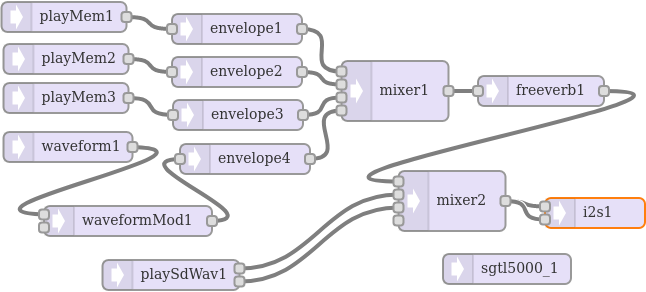
Audio Design Tool makes it easy to create an audio processing system which streams sound while your program runs.
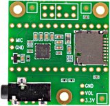
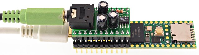
Audio Shield converts I2S digital audio to analog stereo input & output.
- I2S / TDM
- Most commonly used with the audio shield, 2 digital audio ports can simultaneously transmit and receive up to 8 audio channels using I2S protocol, or up to 16 channels using TDM. Alternately, a special format used by inexpensive PT8211 DAC chips can be used.
- I2SI - 1 stereo output pin, 1 stereo input pin, 3 stereo input or output pins
- I2S2 - 1 stereo output pin, 1 stereo input pin
- S/PDIF
- The I2S port may be used to receive and transmit S/PDIF. The S/PDIF is independent of both I2S/TDM ports and can be used simultaneously. Either or both of the I2S ports may also be used to transmit S/PDIF.
- Analog Input (ADC)
- 1 analog input pins may be used for audio inputs. Using an ADC pin for audio input currently has only "experimental" software support.
- MQS Output
- (info here)
PT8211 is the least expensive DAC for good quality stereo signal output
Lights & LEDs
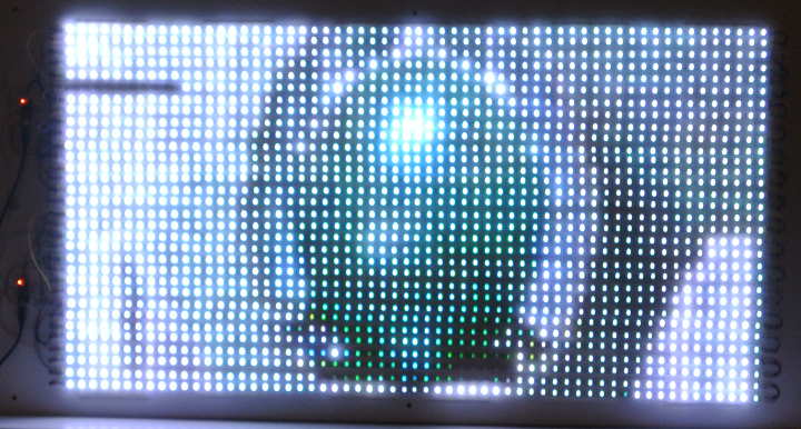
OctoWS2811 Library controlling 1920 WS2812B RGB LEDs at 30 Hz refresh rate
- WS2812B / NeoPixel
- Two high performance non-blocking libraries support use of WS2812B LEDs. OctoWS2811 transmits any number of outputs in parallel, allowing almost any number LEDs to be refreshed at up to 30 Hz video rate. On Teensy 4.1, OctoWS2811 supports use of any number of digital pins, not limited to only 8 pins as on Teensy 3.x. WS2812Serial transmits a single output, but up to 8 instances may be used. Non-blocking transmission uses DMA to transmit automatically, while your code is able to continue running. This much more allows complex animations or efficent communication than traditional blocking.
- SmartMatrix LED Panels
- (info here)
- DMX Lighting Control
- Serial1 & Serial2 may be used for efficient communication with DMX lighting controllers.
- RGB LEDs
- Ordinary LEDs by be variable-brightness controlled by PWM, or the SoftPWM & ShiftPWM libraries.
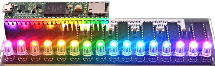
ShiftPWM controlling 16 RGB LEDs using six 74HCT595 chips
Timing
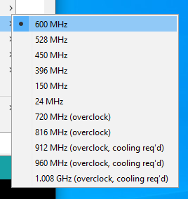
Tools > USB Speed menu configures the speed Teensy 4.1 will run your code.
- Crystals & Clock Generation
- Two crystals prodvide accurate timing. A 24 MHz crystal is the basis for the system clock and most peripherals. A phase locked loop (PLL) increases the 24 MHz up to the system clock speed. A separate 32.768 kHz crystal is used for the Real Time Clock (RTC). If a coin cell is added to VBAT, the 32.768 kHz oscillator continues keeping date/time while main power is off.
- Interval Timers
- 4 timers are dedicated to running a function at precisely timed intervals. These are configured using the IntervalTimer class.
- PWM Timers
- 32 timers control PWM pins, or may be used for other timing functions. Normally these timers are accessed with analogWrite or libraries, but they have many very advanced features which may be accessed by direct hardware register use.
- FlexPWM1 Module0 - Controls PWM pins 1, 44, 45.
- FlexPWM1 Module1 - Controls PWM pins 0, 42, 43.
- FlexPWM1 Module2 - Controls PWM pins 24, 46, 47.
- FlexPWM1 Module3 - Controls PWM pins 7, 8, 25.
- FlexPWM2 Module0 - Controls PWM pins 4, 33.
- FlexPWM2 Module1 - Controls PWM pin 5.
- FlexPWM2 Module2 - Controls PWM pins 6, 9.
- FlexPWM2 Module3 - Controls PWM pins 36, 37.
- FlexPWM3 Module0 - Controls PWM pin 53.
- FlexPWM3 Module1 - Controls PWM pins 28, 29.
- FlexPWM3 Module2 - No pins accessible.
- FlexPWM3 Module3 - Controls PWM pin 41.
- FlexPWM4 Module0 - Controls PWM pin 22.
- FlexPWM4 Module1 - Controls PWM pin 23.
- FlexPWM4 Module2 - Controls PWM pins 2, 3.
- FlexPWM4 Module3 - No pins accessible.
- QuadTimer1 Module0 - Controls PWM pin 10.
- QuadTimer1 Module1 - Controls PWM pin 12.
- QuadTimer1 Module2 - Controls PWM pin 11.
- QuadTimer1 Module3 - No pins accessible.
- QuadTimer2 Module0 - Controls PWM pin 13.
- QuadTimer2 Module1 - No pins accessible.
- QuadTimer2 Module2 - No pins accessible.
- QuadTimer2 Module3 - No pins accessible.
- QuadTimer3 Module0 - Controls PWM pin 19.
- QuadTimer3 Module1 - Controls PWM pin 18.
- QuadTimer3 Module2 - Controls PWM pin 14.
- QuadTimer3 Module3 - Controls PWM pin 15.
- QuadTimer4 Module0 - No pins accessible. Used by OctoWS2811 library
- QuadTimer4 Module1 - No pins accessible. Used by OctoWS2811 library
- QuadTimer4 Module2 - No pins accessible. Used by OctoWS2811 library
- QuadTimer4 Module3 - No pins accessible. Used by Audio for ADC timing.
- Watchdog Timer
- 3 separate watchdog timer are meant to reboot Teensy if your software crashes or gets stuck. Once started, the watchdog timer must be periodically reset. If the software stops resetting the timer for too long, Teensy reboots.
- Special Timers
- These extra timers allow delays, analog sample rate timing, carrier modulation, and other special timing tasks to be performed, without consuming any of the normal PWM-oriented timers.
- GPT1 - Generic 32 bit timer
- GPT2 - Generic Generic 32 bit Timer
- Quadrature Encoders - 4 special timers are meant for decoding quadrature signals.
- Cycle Counter
- A 32 bit counter increments every CPU clock cycle (600 MHz). ARM_DWT_CYCCNT may be read by programs to precisely measure short time duration time.
- SysTick
- This system timer generates an interrupt every millisecond. Most of the software timing features use this Systick timer.
- Software Timing
- Many common timing requirements can be met using the software timing features.
- delay(), delayMicroseconds(), delayNanoseconds() - Simple delay for milliseconds, microseconds, or nanoseconds.
- elapsedMillis, elapsedMicros - These C++ classes act as a variable which automatically increments ever millisecond or microsecond. These can be written or modified as needed, which greatly simplifies implementation of repetitive tasks, measuring elapsed time, inactivity timeouts, and so on. The number of these variable is only limited to the available memory.
- millis(), micros() - Stardard Arduino functions for the system time in milliseconds and microseconds.
- Real Time Clock - Date & Time
- The RTC keeps track of date / time. The Time library is typically used together with the RTC. Teensy Loader automatically initializes the RTC to your PC's time while uploading. If a coin cell is connected to VBAT, the RTC will continue keeping time while power is turned off.
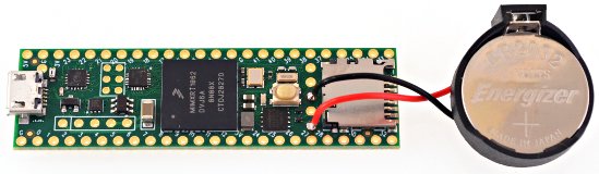
CR2032 Coin Cell connected to VBAT allows Teensy 4.1 to keep date / time while power is off
Power
- USB Power
- Normally Teensy is powered by your PC or USB hub, through a USB cable. The USB power arrives at the VUSB pin, which is connected VIN and powers the entire board.
- VIN Pin
- When USB power is not used, 5V power may be applied to the VIN pin.
- 3.3V Power
- Teensy 4.1 has a voltage regulator which reduces the 5V VUSB / VIN power to 3.3V for use by the main processor and most other parts. Additional circuitry may be powered from the 3.3V pin. The recommended maximum for external 3.3V usage is 250mA. Teensy 4.1 is not meant to receive power on its 3.3V pin, but this can be done with special modificaton (TODO: link to forum thread)
- USB Host Hot Plugging
- Power to USB devices connected on the USB host port is provided through a current limited switch and a large capacitor. The current limit lessens the disruption to Teensy's power when a USB device is hot plugged and needs a sudden inrush current to charge up all its capacitors.
- Power Consumption
- (info here - significantly lower at 528 MHz)
- Low Power Features
- (info here - Snooze library)
- CPU Voltage Control
- (info here)
- VBAT
- A 3 volt coin cell may be connected to VBAT & GND to allow the RTC to keep track of date / time while power is off. A CR2032 type battery is recommended, though other 3V coin cells may also be used.
- On / Off Pin and Power Control
- (info here)
Memory
- TODO: memory map diagram
- Program / Flash Memory
- Teensy 4.1 has 8 Mbyte of flash memory intended for storing your code. The flash memory can also store read-only variables and arrays. A portion of the flash memory may be used for file storage using the LittleFS library.
- RAM
- 1024K of memory is available for variables and data. Half of this memory is accessed as tightly coupled memory for maximum performance.
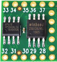
QSPI PSRAM & Flash
- EEPROM
- 4284 bytes of emulated EEPROM memory is supported. Writing to this memory temporarily stalls code execution from flash. The EEPROM library is typically used to access this memory. AVR libc functions may also be used.
- QSPI Memory Expansion
- (info here)
- RTC RAM
- 4 bytes of memory are located within the RTC. If a coin cell is connected to VBAT, contents of this memory is preserved while power is off.
- SD Card
- A built in SD socket allows you to use SD cards for large data storage. The Arduino SD library is used to access the card, using SD.begin(BUILTIN_SDCARD). This built in SD socket uses fast 4 bit native SDIO to access the card. SD cards may also be used via the SPI pins, with SD.begin(cspin), using the slower single bit SPI protocol to access the card.
- SPI Flash
- Flash memory chips may be added using the SPI pins. These are supported by the SerialFlash and LittleFS libraries.
- TODO: internal bus structure diagram
Programming
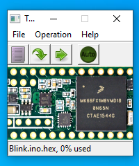
Teensy Loader Application
- Teensy Loader
- Programming of Teensy's flash memory is done by the Teensy Loader application. Normally the Arduino IDE or other software is used to compose code, and it automatically runs Teensy Loader as needed. If you have compiled code in HEX file format, Teensy Loader can be used stand-alone to write your HEX file into Teensy's flash memory.
- Automatic Software Entry to Program Mode
- While developing with Teensy, loading normally happens automatically after compiling your program. A "teensy_reboot" utility looks for your Teensy on all USB ports and sends a request (serial baud rate or HID feature report) to automatically switch to programming mode.
- Program Pushbutton / Pin
- If code previously written to Teensy is not listening for USB communication, automatic entry to programming mode is not possible. A physical pushbutton is provided to allow recovery from bad code. Pressing the button button puts Teensy into programming mode. It is not a "reset button" which restarts your program. The button is dedicated to recovery from bad code. A Program pin also allows external hardware to force entry to programming mode.
- Red LED: Bootloader Active & Flash Writing
- (info here)
- Reset
- An active-low reset pin allows rebooting, which restarts the program loaded in Teensy's flash memory.
- Memory Wipe
- Teensy 4.1 will fully erase its non-volatile memory and return the flash memory to a simple LED blink program if the program button is held between 13 to 17 seconds. The red LED flashes briefly at the beginning of this time window. During flash erase, the red LED is on bright. When completed, Teensy 4.1 will automatically reboot and run the LED blink program, causing the orange LED to blink slowly.
- Bootloader Chip
- Teensy 4.1's bootloader is stored in a dedicated chip. All of the main chip's memory is available to your program. Upon power up, your program runs immediately. The bootloader does not run automatically at startup, as is done with most Arduino compatible boards. The physically separate chip keeps Teensy's bootloader separate from your code and prevents flash programming from being able to damage or erase the bootloader.
- Code Security
- Teensy 4.1 does not currently support code security, encryption or authentication. Support for these features is planned for future boards.
Special Features
- Nested Interrupt Controller
- Priority nesting allows low latency for critical interrupts while lower priority interrupts are in use. Teensyduino's libraries utilize interrupt nesting with priority level defaults which allow many types of libraries to work well when used together.
- Direct Memory Access (DMA)
- Teensy 4.1 has a general purpose 32 channel DMA controller. Optimized Audio, LED and display libraries make uses of these DMA channels. A DMAChannel.h abstraction layer is provided. The USB device, USB host, SD card and Ethernet peripherals also have specialized DMA engines built in.
- Random Number Generator
- True random number hardware is capable of generating random data at (TBD) rate. The Entropy library is used to access the random number generator.
- Cryptographic Acceleration
- Symetric ciphers and one-way hash can be computed by hardware, but currently no library support exists to utilize this hardware.
- Temperature Sensor
- A built in temperature sensor allows reading the temperature inside the main chip. The InternalTemperature library can be used to access this sensor.
| Part Number | TEENSY41 |
|---|---|
| Manufacturer | PJRC |
| Weight (KG) | 0.005000 |
| Product Availability | In Stock |
Write Your Own Review
Related Products
Check items to add to the cart or

We found other products you might like!
-
 Teensy++ 2.0 AVR ISP AT90USB1286 Development BoardSpecial Price PKR 2,450.00 Regular Price PKR 3,750.00
 -
 Teensy 3.6 Development Board Without Header MK66FX1M0VMDPKR 13,200.00
 -
 Teensy 4.0 Development Board with ARM Cortex-M7 Processor 600MHzSpecial Price PKR 10,800.00 Regular Price PKR 12,200.00