We use cookies to make your experience better. To comply with the new e-Privacy directive, we need to ask for your consent to set the cookies. Learn more.
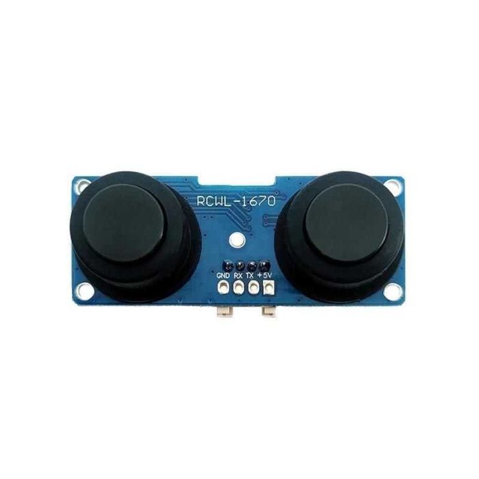
Ultrasonic with Microwave Radar Distance Range Finder Sensor 400cm - RCWL-1670
PKR 1,850.00
SKU
MD-02224
- Buy 3 for PKR 1,757.50 each and save 5%
- Buy 10 for PKR 1,702.00 each and save 8%
Introduction
The RCWL-1670 ultrasonic sensor is a sophisticated motion detection component that integrates ultrasonic sensing with microwave radar technology. This sensor is capable of detecting motion through the measurement of changes in high-frequency radio waves and ultrasonic waves, offering a reliable method for sensing movement within its detection range. It is commonly used in applications such as automatic lighting, security systems, and industrial automation.
Common Applications and Use Cases
- Automated lighting control
- Security and surveillance systems
- Proximity detection for robotics
- Industrial equipment motion sensing
- Home automation systems
Technical Specifications
Key Technical Details
- Operating Voltage: 4.5V to 28V
- Operating Current: 2.8mA (typical)
- Detection Angle: 360° (spherical)
- Detection Range: 5 to 7 meters
- Frequency: 3.2GHz microwave radar, 40kHz ultrasonic
- Output Type: Digital signal (high/low)
Pin Configuration and Descriptions
| Pin Number | Name | Description |
|---|---|---|
| 1 | VCC | Power supply input (4.5V to 28V) |
| 2 | GND | Ground connection |
| 3 | OUT | Digital output signal (high when motion is detected) |
| 4 | CDS | Light-dependent resistor (LDR) input for enabling operation in darkness |
Usage Instructions
How to Use the Component in a Circuit
- Power Supply: Connect the VCC pin to a power source within the range of 4.5V to 28V. Ensure that the power supply can provide sufficient current for the sensor's operation.
- Ground Connection: Connect the GND pin to the ground of the power supply and your circuit's common ground.
- Output Signal: Connect the OUT pin to a digital input pin on a microcontroller, such as an Arduino, to read the sensor's output.
- LDR Input (Optional): If you want the sensor to operate only in low light conditions, connect a light-dependent resistor to the CDS pin.
Important Considerations and Best Practices
- Ensure that the sensor is mounted in a stable position to avoid false triggers due to its own movement.
- Avoid placing the sensor near objects that can reflect or absorb ultrasonic waves, as this can affect its accuracy.
- The sensor's detection range can be influenced by environmental conditions such as temperature and humidity.
- Use appropriate decoupling capacitors near the power supply pins to minimize power supply noise.
Troubleshooting and FAQs
Common Issues Users Might Face
- False Triggers: Ensure that the sensor is not facing any moving objects within its detection range that could cause unintended activation.
- No Output Signal: Check the power supply connections and ensure that the voltage is within the specified range. Also, verify that the microcontroller is correctly reading the digital output pin.
- Limited Detection Range: Adjust the sensor's position or orientation to optimize its detection range. Environmental factors may also affect the range.
Solutions and Tips for Troubleshooting
- If the sensor is not functioning as expected, double-check all connections and ensure that the power supply is stable and within the specified voltage range.
- Use a multimeter to verify that the sensor is receiving power and that the output signal is changing when motion is detected.
- For issues with the microcontroller interface, ensure that the correct digital pin is being used and that the microcontroller's code is properly configured to read the sensor's output.
Example Arduino Code
// Define the RCWL-1670 output pin
const int sensorPin = 2;

void setup() {
  // Initialize the sensor output pin as an input
  pinMode(sensorPin, INPUT);
  // Begin serial communication at 9600 baud rate
  Serial.begin(9600);
}

void loop() {
  // Read the sensor output
  int sensorValue = digitalRead(sensorPin);
  // If motion is detected, the output pin goes HIGH
  if (sensorValue == HIGH) {
    Serial.println("Motion detected!");
  } else {
    Serial.println("No motion detected.");
  }
  // Wait for a short period before reading again
  delay(500);
}
Note: The above code is a simple example to demonstrate how to interface the RCWL-1670 ultrasonic sensor with an Arduino UNO. The sensorPin should be connected to the OUT pin of the sensor, and the sensor should be powered according to the technical specifications. Adjust the delay as needed for your specific application.
| Part Number | RCWL-1670 |
|---|---|
| Weight (KG) | 0.030000 |
| Packing Unit | 1 Piece |
| Product Availability | In Stock |
Write Your Own Review
Related Products
Check items to add to the cart or
-
 Ultrasonic Distance Measuring Sensor Module HC-SR04Special Price PKR 170.00 Regular Price PKR 180.00
 -
 URM Ultrasonic Mounting Bracket For HC-SR04 US-100Special Price PKR 55.00 Regular Price PKR 65.00
 -
 DFRobot: Fermion Ultrasonic Sensor URM37 (2-800cm) - SEN0001Special Price PKR 5,400.00 Regular Price PKR 6,200.00