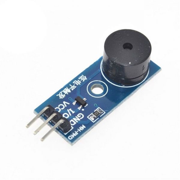
Passive Buzzer Module Low Trigger for Arduino/Raspberry Pi
A passive buzzer (AKA magnetic transducer) can make different tones, but the devices that control the buzzer has to provide it with an oscillating electronic signal at the desired frequency. The supplied frequency will determine the tone. Supplying just a fixed voltage will generate no sound, except perhaps a slight "tick" at the point when the power source is connected or disconnected from the buzzer.
This Module is Low-Level Trigger using its Low-Level Trigger transistor
1, there is no shock source inside the passive, so if it can't between by DC signal. A square wave of 2K~5K must be used to drive it
2, in some special cases, a control port can be multiplexed with LED.
3, voice frequency controllable, can make "to send Tracy cable" effect.
The characteristics of the active buzzer are:
1, the active buzzer has a shock source inside, so it will be called as long as it is electrified.
2, program control is convenient. A high and low level of MCU can make it sound, but passive buzzer can not do it.
A module description
The 1 module is driven by the 9012 triode
6 with fixed bolt holes for easy installation
7 small size: 3.3cm * 1.3cm PCB
Two module interface description (3 wire system)
2 working voltage 3.3V-5V
1 VCC external 3.3V-5V voltage (directly connected to 5V microcontroller and 3.3V microcontroller).
2 GND outside GND
3 I/O external chip IO port
Controlling the buzzer by Arduino (AKA driving the buzzer)
An Arduino can generate an oscillating signal as required by a passive buzzer. The signal can be emitted at one of the digital pins. However, an Arduino can only provide up to about 40mA of current on each of its pins.
If you require a louder sound, or if your buzzer requires higher currents than an Arduino can safely supply you can add a transistor to the circuit. You can always use a DMM to measure how much current your buzzer takes when it is driven through a transistor and compare it to Arduino's max current. When doing the calculations, mind that for the oscillating signal, the measured average current will be half of the actual peak current.
The signal from Arduino will connect to the base of the transistor through a base resistor and will open/close the transistor to allow higher current flow from the power source to power the buzzer. When using a transistor you can use lower value series resistors or you can even try none at all.
Popular buzzers are usually 16Ω and usually take as much as 100mA when making a sound (without an additional series resistor).
| Part Number | NA |
|---|---|
| Manufacturer | Made in China |
| Weight (KG) | 0.010000 |
| Packing Unit | 1 Piece |
| Product Availability | In Stock |


Log In