Maxim Integrated - 8-Channel Digital Output Micro PLC Card MAXREFDES63#

- Buy 3 for PKR6,400.00 each and save 66%
- Buy 10 for PKR6,150.00 each and save 67%
Introduction
Industry 4.01 marks the fourth industrial revolution, characterized by distributed, intelligent control systems. Breaking from a past with large, centralized programmable-logic controllers, Industry 4.0 allows for highly configurable, highly modular factories, which accept an ever increasing number of sensor inputs, while operating at a higher output than ever before. The ultra-small PLC, or MicroPLC, lies at the heart of the Industry 4.0 factory, providing high performance with ultra-low power consumption, in an ultra-small package. MAXREFDES63# is Maxim Integrated’s Micro PLC octal-channel, digital output card.
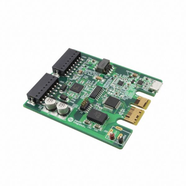
The MAXREFDES63# reference design (Figure 1) features eight-channel digital outputs with isolated power and data. The design integrates a 600VRMS data isolation (MAX14850); a STM32F1 microcontroller; a FTDI USB-UART bridge; a high-efficiency DC-DC converter (MAX17515); and isolated/regulated +22V, and +5V power rails (MAX17498C). The entire system typically operates at less than 400mW and fits into a space roughly the size of a credit card.

Figure 1. The MAXREFDES63# reference design block diagram.
Features
- Isolated power and data
- Micro PLC form factor
- Device drivers
- Example C source code
Applications
- Industrial control and automation
- Process control
- PLC
Detailed Description of Hardware
The power requirement is shown in Table 1.
Table 1. Power Requirement for the MAXREFDES63# Reference Design
| Power Type | Input Voltage (V) | Input Current (mA, typ) |
|---|---|---|
| On-board isolated power | 24 | 15 (All LEDs on) + Load Current |
Note: STM32 and FTDI are powered by USB separately.
The MAX14900 (U400) is an octal power switch with per-channel configuration feature.
The ultra-efficient MAX17498C (U102) generates the isolated +22V, and +5V rails from a 24V supply. The MAX14850 (U301) digital data isolators provide data isolation. The combined power and data isolation achieved is 600VRMS.
The MAX17515 (U101) step-down DC-DC converter converts the +5V supply from the USB to +3.3V and powers the STM32 (U1) microcontroller and FTDI (U201) USB-UART bridge.
Detailed Description of Firmware
The MAXREFDES63# uses the on-board STM32F1 microcontroller to communicate with the octal power switch. The user enters configuration data through a terminal program and the digital outputs will be updated. The simple process flow is shown in Figure 2. The firmware is written in C using the Keil µVision5 tool.

Figure 2. The MAXREFDES63# firmware flowchart.
The complete source code is provided to speed up customer development. Code documentation can be found in the corresponding firmware platform files.
Quick Start
Required equipment:
- Windows® PC with a USB port
- MAXREFDES63# board
- 24V power supply
Procedure
The complete source code is provided to speed up customer development. Code documentation can be found in the corresponding firmware platform files.
- Turn off or keep off the 24V power supply.
- The MAXREFDES63# utilizes the FTDI USB-UART bridge IC. If Windows cannot automatically install the driver for the FTDI USB-UART bridge IC, the driver is available for download from www.ftdichip.com/Drivers/D2XX.htm.
- Connect the negative terminal of the 24V power supply to the PGND connector on the MAXREFDES63# board. Connect the positive terminal of the 24V power supply to the +24V connector on the MAXREFDES63# board.
- Turn on the 24V power supply.
- Connect the USB cable from the PC to the MAXREFDES63# board.
- Open Hyperterminal or similar Terminal program on the PC. Find the appropriate COM port, usually a higher number port, such as COM4, or COM6, and configure the connection for 921600, n, 8, 1, none (flow control).
- The MAXREFDES63# software will display a menu (Figure 3)
- Press any key in the terminal program to start the output configuration.
- Enter the Configuration Byte in hex format.
- Enter the desired output data in hex format.
- Verify the output status by observing the 8 green LEDs under connectors J400 and J401 on the board. These LEDs are connected to the digital outputs of the card.

Figure 3. Terminal program main menu.
Lab Measurements
Figure 4 and Figure 5 shows the status of the LEDs with the output configuration byte set to 0xFF and the output data byte set to 0xAA.

Figure 4. Test setup.

Figure 5. Test outputs.
| Part Number | MAXREFDES63# |
|---|---|
| Manufacturer | Maxim Integrated |
| Weight (KG) | 0.100000 |
Log In